A technician connects a mechanical vacuum gauge to the intake manifold of an engine idling at 650 RPM. The gauge needle remains perfectly steady but indicates only 12 in. Hg, well below the normal specification of 18–20 in. Hg. As engine speed increases, the vacuum reading rises smoothly. Which of the following is the most likely cause of this steady, abnormally low vacuum reading?
Answer and explanation
Correct answer: A
Retarded camshaft timing prevents cylinders from drawing a full vacuum stroke, yielding a steady but uniformly low manifold vacuum reading. Manifold leaks typically cause a rough idle, while valvetrain faults cause needle fluctuation.
Q2Question 2
Intermediate
Engine Repair · General Engine Diagnosis
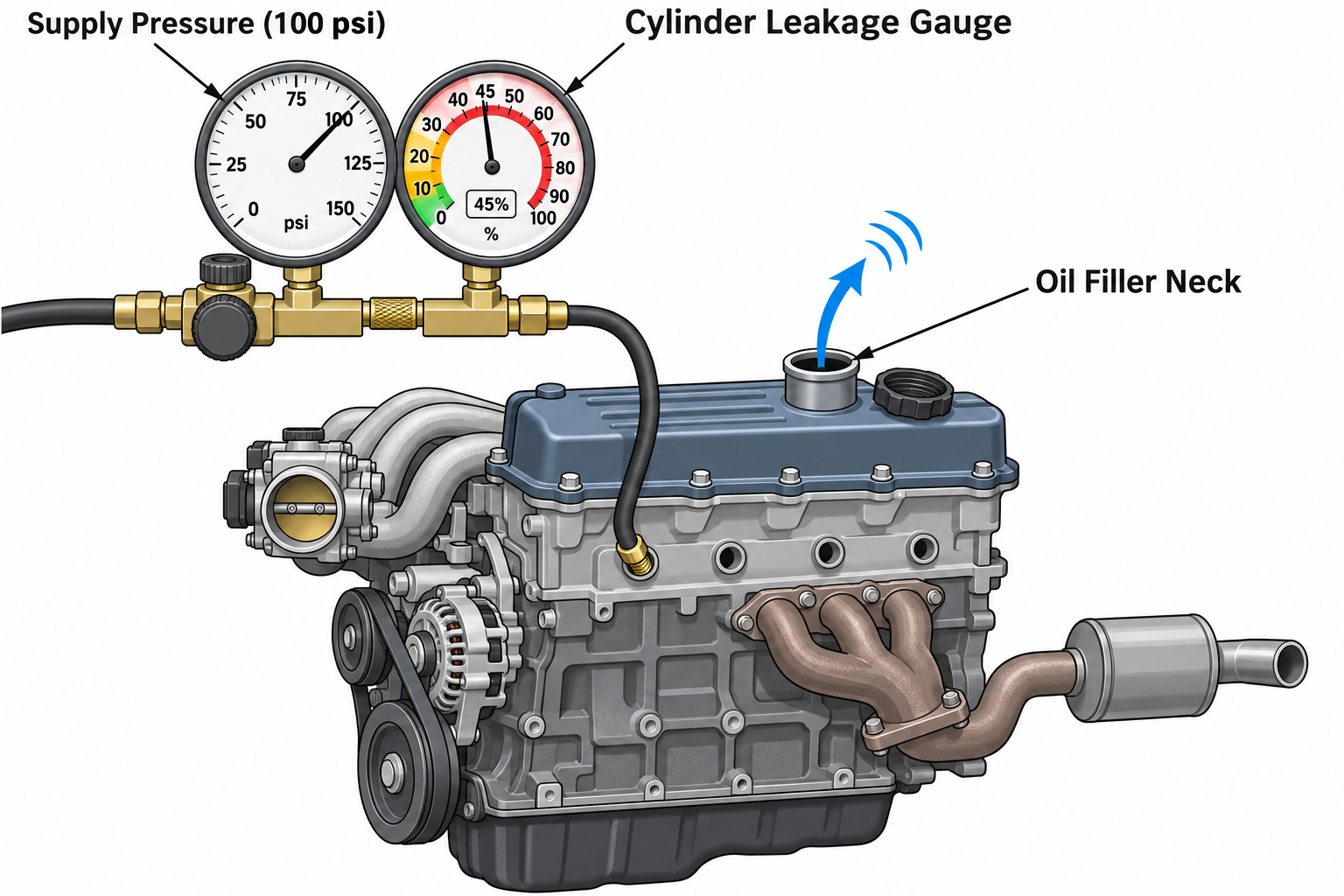
A technician performs a cylinder leakage test on cylinder #4 of a V6 engine after a cranking compression test revealed 65 psi compared to 175 psi on all other cylinders. With the piston positioned at top dead center (TDC) compression and 100 psi applied to the tester, the results shown in the figure are observed, with air audibly escaping from the open engine oil filler neck. What is the most likely cause?
Answer and explanation
Correct answer: A
Air escaping through the oil filler neck during a cylinder leakage test at TDC compression indicates air is blowing past the piston rings into the crankcase. Air from the tailpipe would indicate exhaust valve leakage.
Q3Question 3
Beginner
Engine Repair · General Engine Diagnosis
True or False: Performing a relative compression test using a digital storage oscilloscope (DSO) and a high-amp clamp around the starter motor positive cable relies on starter current draw variations to detect cylinders with mechanical sealing defects.
Answer and explanation
Correct answer: B
True. Relative compression testing measures starter current peaks per cylinder compression stroke; a cylinder lacking mechanical compression requires less cranking torque and creates a lower starter amperage peak.
Q4Question 4
Advanced
Engine Repair · General Engine Diagnosis
A 2021 full-size light-duty truck equipped with a 5.3L V8 engine is brought into the service department. The driver reports a sudden loss of engine power while towing on the highway, accompanied by a flashing Malfunction Indicator Lamp (MIL) and an audible mechanical ticking from the engine compartment that increases in frequency with engine speed. The vehicle now runs rough at idle and stalls occasionally when coming to a stop.
The technician connects a scan tool and retrieves diagnostic trouble code P0301 (Cylinder 1 Misfire Detected) along with P3401 (Cylinder 1 Deactivation/Intake Valve Control Circuit/Open). Freeze frame data shows the misfire occurred at 2,400 RPM under a 72% engine calculated load. A cylinder power balance test confirms that cylinder #1 contributes zero torque to crankshaft rotation. A manual cranking compression test yields 0 psi on cylinder #1, while cylinders #3, #5, and #7 all measure between 175 and 180 psi.
Next, the technician removes the driver-side valve cover and cranks the engine while inspecting valvetrain movement. The intake valve rocker arm on cylinder #1 fails to actuate entirely, remaining stationary, while the pushrod rotates freely and exhibits excessive clearance beneath the rocker arm. What corrective action is required?
Answer and explanation
Correct answer: B
A stationary rocker arm with excessive pushrod clearance and 0 psi compression on a displacement-on-demand engine indicates a collapsed cylinder deactivation (AFM/DFM) roller lifter that failed to lock into its high-lift state.
A rear-wheel-drive 6-speed automatic transmission slips excessively during the 2–3 upshift under light acceleration, but operates properly in 1st, 2nd, and reverse gears. The transmission control module (TCM) stores diagnostic trouble code P0733 (Gear 3 Incorrect Ratio). Line pressure testing confirms that main line pressure remains within factory specifications across all ranges.
Review the hydraulic clutch apply logic shown below:
flowchart LR
A[Gear Range] --> B[Clutch Apply Requirements]
B --> C["1st: Forward Clutch + Low/Reverse Brake"]
B --> D["2nd: Forward Clutch + 2-6 Brake"]
B --> E["3rd: Forward Clutch + 3-5-Reverse Clutch"]
B --> F["4th: Forward Clutch + 4-5-6 Clutch"]
B --> G["Reverse: 3-5-Reverse Clutch + Low/Reverse Brake"]
Given this hydraulic application schedule, which component is the most likely cause of the 2–3 shift flare and slippage?
Answer and explanation
Correct answer: B
The 3-5-Reverse clutch is newly applied in 3rd gear. If its piston seal leaks, line pressure drops in that circuit, causing shift flare into 3rd gear. Forward clutch is common to 1st, 2nd, and 3rd, so it would slip in all forward gears.
A technician is checking the automatic transmission fluid (ATF) level on a late-model vehicle that does not feature a conventional dipstick tube. The transmission case utilizes a bottom check plug (standpipe). Which TWO conditions must be verified before removing the level check plug to ensure an accurate fluid level measurement? (Select TWO)
Answer and explanation
Correct answers: A, B
Non-dipstick transmissions require the vehicle to be level and the fluid within an exact scan tool temperature range because ATF expands significantly as it heats; the engine must idle in Park or Neutral during check.
Register free for 6 more questions
Or unlock all 156 A1-A9 questions with explanations, timed mode and flashcards.